Additional Description
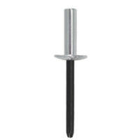
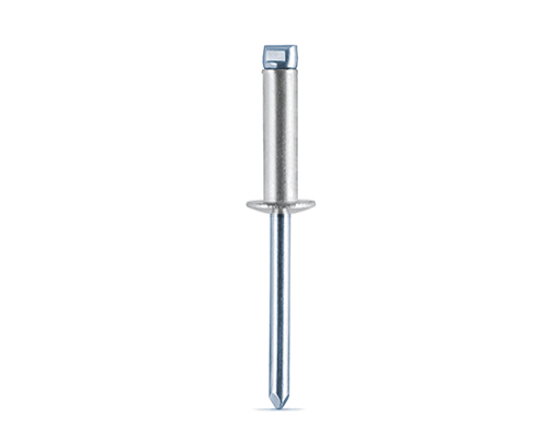
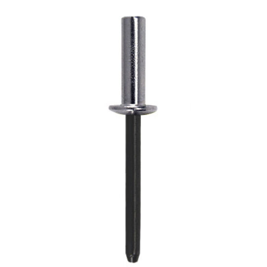
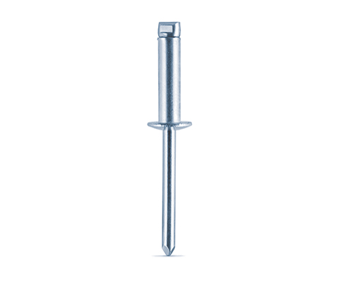
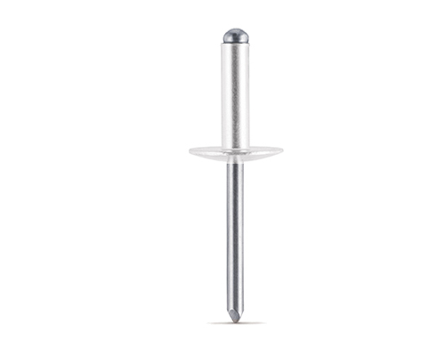
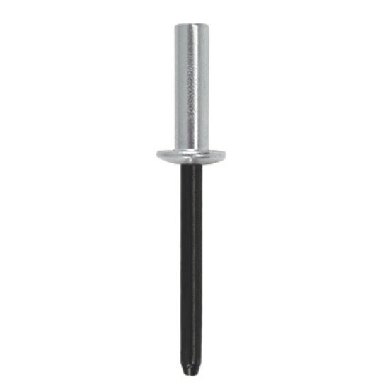
ABS-CE-LF Closed End Aluminum/Steel Large Flange Head
ABS-CE-LF Closed End Aluminum/Steel Large Flange Head
Closed end blind rivets, also called sealed rivets are designed with a solid end to ensure 100% mandrel retention and eliminate leaks that is a common problem with open end rivets. After application of the rivet, the hole in the fastened joint will be completely sealed which prevents fluids or vapor from passing. This can further be improved by application of a plastisol gasket under the head, especially in critical applications. Closed end rivets work well in electronic applications or where vibration is of concern because the remaining mandrel is locked in the rivet body which prevents loosening or grounding problems for electrical components. Our Rivets are tested in New Jersey to ensure consistent, error-free application.
Optional Finishes:
- Color Matched Painting
- Products
- Product Assistance
- Description
- Design Considerations
- CAD Files
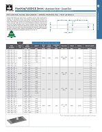
- Catalog
| Part Number | Diameter | Grip | MAX | MAX | Hole Size | Drill Size | |
| Body | Head | Head | |||||
| Length | Diameter | Height | |||||
| ABS32CELF/IR | 3/32” | .020 – .125 | — | .269 – .293 | 0.065 | — | — |
| ABS34CELF/IR | 3/32” | .126 – .250 | — | .269 – .293 | 0.065 | — | — |
| ABS41CELF/IR | 1/8” | .020 – .062 | .297 | .360 – .390 | 0.075 | .129 – .133 | #30 |
| ABS42CELF/IR | 1/8” | .020 – .125 | .360 | .360 – .390 | 0.075 | .129 – .133 | #30 |
| ABS43CELF/IR | 1/8” | .020 – .187 | .422 | .360 – .390 | 0.075 | .129 – .133 | #30 |
| ABS44CELF/IR | 1/8” | .188 – .255 | .485 | .360 – .390 | 0.075 | .129 – .133 | #30 |
| ABS45CELF/IR | 1/8” | .251 – .312 | .547 | .360 – .390 | 0.075 | .129 – .133 | #30 |
| ABS46CELF/IR | 1/8” | .313 – .375 | .610 | .360 – .390 | 0.075 | .129 – .133 | #30 |
| ABS48CELF/IR | 1/8” | .376 – .500 | .735 | .360 – .390 | 0.075 | .129 – .133 | #30 |
| ABS410CELF/IR | 1/8” | .501 – .625 | .760 | .360 – .390 | .075 | .160 – .164 | #30 |
| ABS52CELF/IR | 5/32” | .020 – .125 | .375 | .448 – .488 | 0.085 | .160 – .164 | #20 |
| ABS53CELF/IR | 5/32” | .126 – .187 | .437 | .448 – .488 | 0.085 | .160 – .164 | #20 |
| ABS54CELF/IR | 5/32” | .188 – .250 | .500 | .448 – .488 | 0.085 | .160 – .164 | #20 |
| ABS56CELF/IR | 5/32” | .376 – .500 | .562 | .448 – .488 | 0.085 | .160 – .164 | #20 |
| ABS58CELF/IR | 5/32” | .626 – .750 | .625 | .448 – .488 | 0.085 | .160 – .164 | #20 |
| ABS510CELF/IR | 5/32” | .501 – .625 | .750 | .448 – .488 | 0.085 | .192 – .196 | #20 |
| ABS512CELF/IR | 5/32” | .626 – .750 | .875 | .448 – .488 | 0.085 | .192 – .196 | #20 |
| ABS62CELF/IR | 3/16” | .020 – .125 | .406 | .600 – .650 | 0.095 | .192 – .196 | #11 |
| ABS63CELF/IR | 3/16” | .126 – .187 | .468 | .600 – .650 | 0.095 | .192 – .196 | #11 |
| ABS64CELF/IR | 3/16” | .188 – .250 | .531 | .600 – .650 | 0.095 | .192 – .196 | #11 |
| ABS66CELF/IR | 3/16” | .251 – .375 | .656 | .600 – .650 | 0.095 | .192 – .196 | #11 |
| ABS68CELF/IR | 3/16” | .376 – .500 | .781 | .600 – .650 | 0.095 | .192 – .196 | #11 |
| ABS610CELF/IR | 3/16” | .501 – .625 | .906 | .600 – .650 | 0.095 | .192 – .196 | #11 |
| ABS612CELF/IR | 3/16” | .626 – .750 | 1.026 | .600 – .650 | 0.095 | .192 – .196 | #11 |
| ABS82CELF/IR | 1/4” | .020 – .125 | .445 | .720 – .780 | 0.11 | .257 – .261 | F |
| ABS84CELF/IR | 1/4” | .126 – .250 | .570 | .720 – .780 | 0.11 | .257 – .261 | F |
| ABS86CELF/IR | 1/4” | .251 – .375 | .695 | .720 – .780 | 0.11 | .257 – .261 | F |
| ABS88CELF/IR | 1/4” | .376 – .500 | .820 | .720 – .780 | 0.11 | .257 – .261 | F |
| ABS810CELF/IR | 1/4” | .501 – .625 | .945 | .720 – .780 | 0.11 | .257 – .261 | F |
| ABS812CELF/IR | 1/4” | .626 – .750 | 1.070 | .720 – .780 | 0.11 | .257 – .261 | F |
Industrial Rivet & Fastener Co. can help you select the right product or tool for your application. Please contact our experienced Product Specialists with any questions. We look forward to hearing from you! 1-800-BUY-RIVET or info@rivet.com
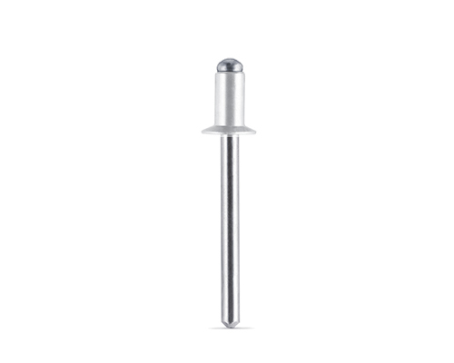
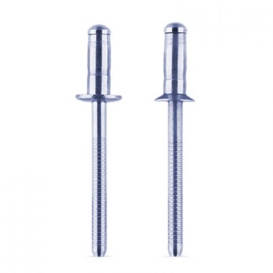
Aluminum/Steel, Closed End Blind Rivets, Countersunk Head, IFI-126, Grade 19
Design Considerations
Grip Range:
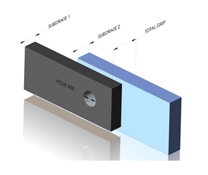
Determining the length of the rivet is critical to ensure the rivet will function as intended. If the rivet is applied over or under its intended grip range, it may not work properly. All manufacturers list a range of material thickness in which the product will perform properly. This thickness is commonly called the grip range. Setting rivets outside of their specified grip range can lead to functional failures. Rivets set over-grip will not retain the mandrel head, causing it to fall out of the rivet body after setting. Rivets set under-grip can bend and offset, reducing the overall strength and aesthetic appearance. Failure to adhere to the grip range may also cause a premature break or difficulty in clearing the spent mandrel from the setting tool.
Also be sure to account for the theoretical grip versus the actual grip. While the grip may be calculated by adding the thickness of the two materials together, be sure to account for any burrs, bends and manufacturing tolerances which may increase or decrease the overall grip of the materials being riveted.
Hole Size:
Hole sizes are extremely important for the proper functionality of blind rivets. We specify a hole size for every rivet we manufacture. A rivet is only guaranteed to function as designed when the hole size is within the prescribed range. Additionally, the design engineer should calculate the manufacturing tolerances of the hole to ensure proper fit so that interference issues will not occur later.
Joint Materials & Strength:
It is sometimes necessary to use dissimilar materials such as fastening aluminum to steel or plastics to aluminum. Whenever possible, the stronger material should be the secondary side because this is where the setting will take place. As a general rule, a rivet should be used in materials equal to or greater than its own strength, although custom rivets can be produced to work in softer materials. Be sure to verify the compatibility of the rivet materials as galvanic corrosion can occur and is seldom considered in the design phase.
Tool Clearance:
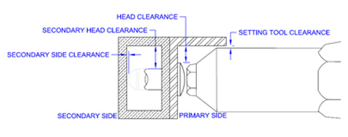
Sufficient clearances are needed so that the tool can access the joint being riveted without interference. Be sure to account for the riveting equipment in the design phase to prevent the need for customized and potentially costly tooling modifications.
Head Clearance:
Axial access is required on the primary side being riveted to allow for the flange to overlap the hole without interference. When designing the primary hole, be sure to calculate the head diameter and its tolerances as well as the layout footprint of the head around the hole. This is especially critical when riveting on brackets and other hardware next to bends, folds, extrusions and/or cutouts on the applications.
Blind Side Clearance:
Since the blind side of the rivet is designed to form into a secondary flange, it is important to leave room for the flange to expand and seat properly. Keep in mind, the collapsed height is shorter than the pre-installed height. Therefore, be sure the secondary side can accommodate the entire rivet length (including the mandrel head), before riveting. Testing should be done in the design phase to calculate what distances are needed and to verify proper functionality.
Corrosion Protection:
The corrosion factor of a particular rivet is dependent on the corrosivities of the base metal, the protective layer (plating) and the conversion layer (chromate). Being that the most cost effective material to manufacture is steel, most prefer to protect the steel with a plating such as Zinc Chromate, or other alloy platings. Because blind rivets are plated before they are assembled, do not attempt to post-plate an assembled rivet. For standard performance, an SST rating of 24 hours until red rust is common. Other platings such as zinc alloys (Zinc Nickel, Zinc Iron, Tin Zinc) are available which can extend the SST rating to 840 hours until red rust. All specified finishes are tested by RivetKing in accordance with ASTM B117 standards.
CAD Files
INCH_ABSCE-ABSLFCE-ACSCE_Dwg_RevG
The following are available for download upon request by emailing engineering@rivet.com
.dxf
.dwg
.IGES
.SLDPRT


