



IHF Series
IHF Series
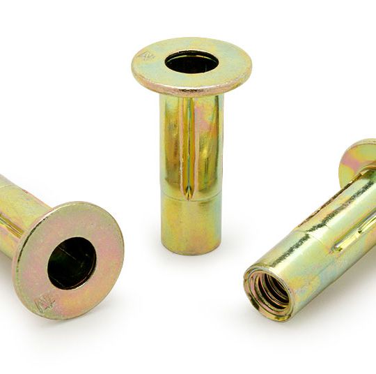
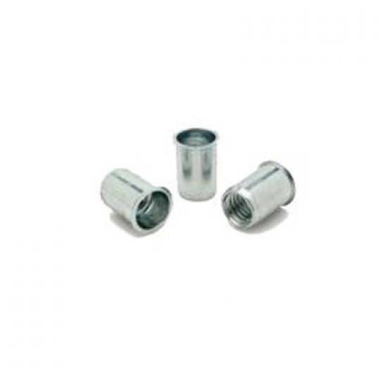
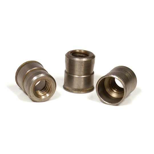
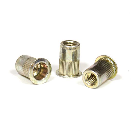
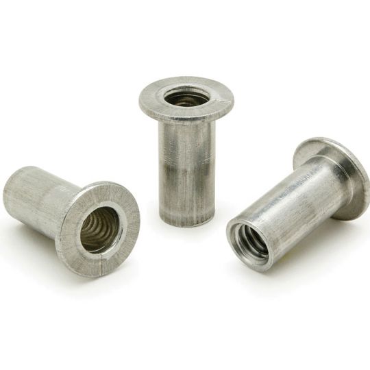
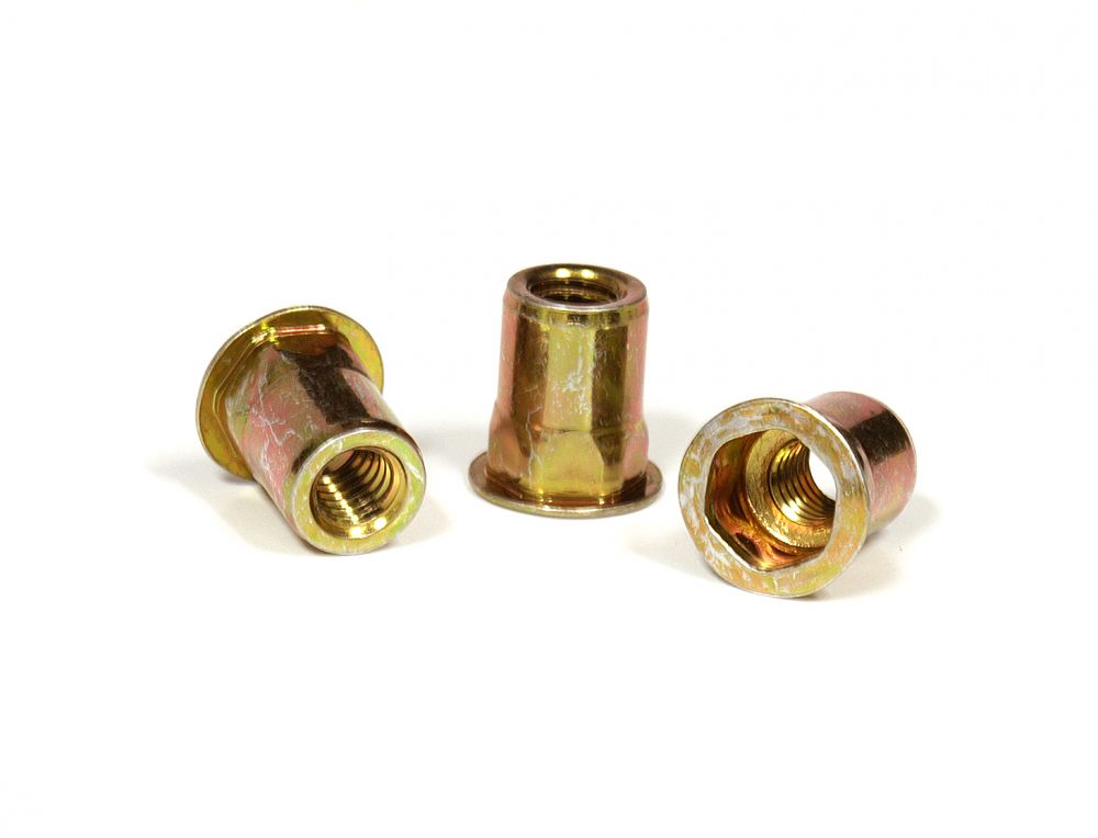
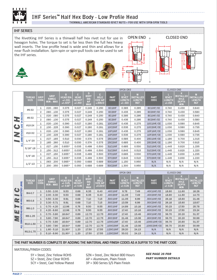
The RivetKing IHF Series is a thinwall half hex insert for use in hexagon holes. The half hex thinwall rivetnut is designed for use with spin-spin tools. The torque to set is far less then the full hex heavy wall inserts. The low profi le head is wide and thin and allows for a near flush installation. Spin-Spin or Spin-Pull tools can be used to set the IHF series.
PROP 65 Warning for STAINLESS STEEL products:
 WARNING: This product contains Nickel, a chemical known to the State of California to cause cancer. For more information go to www.P65Warnings.ca.gov
- Products
- Product Assistance
- Description
- Design Considerations
- CAD Files
- Catalog
IHF Series – Open End (Inch)
| Thread Size |
Grip Range Min – Max |
Part Code |
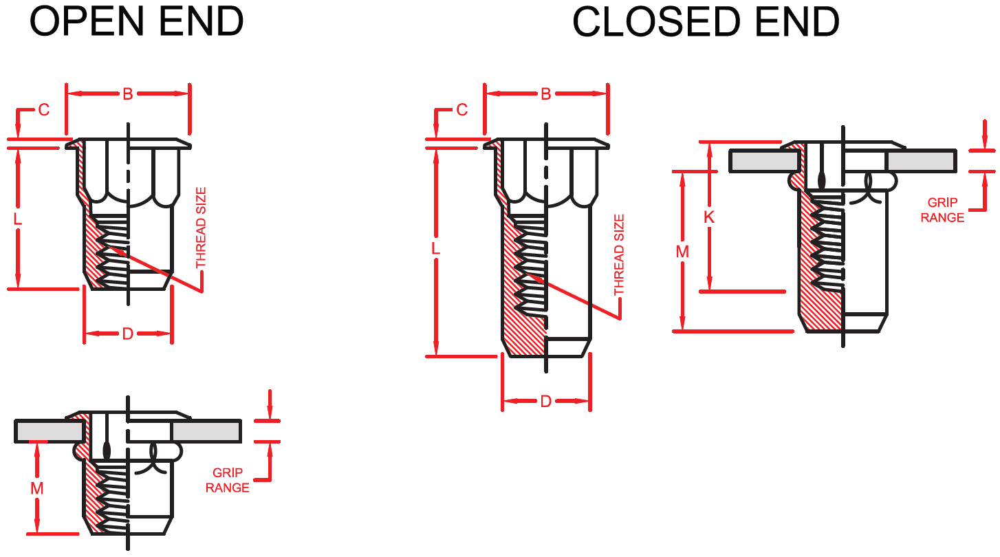
Rivet Length (L) |
Head Dia (B) |
Head Height (C) |
Body Dia (D) |
Installed Length (M) |
Hole Size |
|---|---|---|---|---|---|---|---|---|
| #6-32 | .020 – .080 | 6C1IHF | .385 | .375 | .027 | .249 | .295 | .250 |
| #6-32 | .080 – .130 | 6C2IHF | .435 | .375 | .027 | .249 | .295 | .250 |
| #8-32 | .020 – .080 | 8C1IHF | .385 | .375 | .027 | .249 | .295 | .250 |
| #8-32 | .080 – .130 | 8C2IHF | .435 | .375 | .027 | .249 | .295 | .250 |
| #10-24 | .020 – .130 | 10C1IHF | .435 | .390 | .027 | .280 | .275 | .281 |
| #10-24 | .130 – .225 | 10C2IHF | .535 | .390 | .027 | .280 | .275 | .281 |
| #10-32 | .020 – .130 | 10F1IHF | .435 | .390 | .027 | .280 | .275 | .281 |
| #10-32 | .130 – .225 | 10F2IHF | .535 | .390 | .027 | .280 | .275 | .281 |
| 1/4″-20 | .027 – .165 | 25C1IHF | .585 | .510 | .030 | .374 | .400 | .375 |
| 1/4″-20 | .165 – .260 | 25C2IHF | .685 | .510 | .030 | .374 | .400 | .375 |
| 5/16″-18 | .027 – .150 | 31C1IHF | .685 | .655 | .035 | .499 | .530 | .500 |
| 5/16″-18 | .150 – .312 | 31C2IHF | .845 | .655 | .035 | .499 | .515 | .500 |
| 3/8″-16 | .027 – .150 | 37C1IHF | .685 | .655 | .035 | .499 | .530 | .500 |
| 3/8″-16 | .150 – .312 | 37C2IHF | .845 | .655 | .035 | .499 | .515 | .500 |
| 1/2″-13 | .063 – .200 | 50C1IHF | 1.150 | .865 | .047 | .686 | .850 | .687 |
| 1/2″-13 | .200 – .350 | 50C2IHF | 1.300 | .865 | .047 | .686 | .850 | .687 |
IHF-CE Series – Closed End (Inch)
| Thread Size |
Grip Range Min – Max |
Part Code |
Rivet Length (L-CE) |
Head Dia (B) |
Head Height (C) |
Body Dia (D) |
Installed Hole Depth (K) |
Installed Length (M-CE) |
Hole Size |
|---|---|---|---|---|---|---|---|---|---|
| #6-32 | .020 – .080 | 6C1IHF/CE | .755 | .375 | .027 | .249 | .575 | .640 | .250 |
| #6-32 | .080 – .130 | 6C2IHF/CE | .755 | .375 | .027 | .249 | .640 | .580 | .250 |
| #8-32 | .020 – .080 | 8C1IHF/CE | .755 | .375 | .027 | .249 | .575 | .640 | .250 |
| #8-32 | .080 – .130 | 8C2IHF/CE | .755 | .375 | .027 | .249 | .640 | .580 | .250 |
| #10-24 | .020 – .130 | 10C1IHF/CE | 1.045 | .390 | .027 | .280 | .695 | .845 | .281 |
| #10-24 | .130 – .225 | 10C2IHF/CE | 1.045 | .390 | .027 | .280 | .805 | .735 | .281 |
| #10-32 | .020 – .130 | 10F1IHF/CE | 1.045 | .390 | .027 | .280 | .695 | .845 | .281 |
| #10-32 | .130 – .225 | 10F2IHF/CE | 1.045 | .390 | .027 | .280 | .805 | .735 | .281 |
| 1/4″-20 | .027 – .165 | 25C1IHF/CE | 1.205 | .510 | .030 | .374 | .945 | 1.015 | .375 |
| 1/4″-20 | .165 – .260 | 25C2IHF/CE | 1.205 | .510 | .030 | .374 | 1.085 | .915 | .375 |
| 5/16″-18 | .027 – .150 | 31C1IHF/CE | 1.460 | .655 | .035 | .499 | 1.045 | 1.235 | .500 |
| 5/16″-18 | .150 – .312 | 31C2IHF/CE | 1.460 | .655 | .035 | .499 | 1.170 | 1.220 | .500 |
| 3/8″-16 | .027 – .150 | 37C1IHF/CE | 1.460 | .655 | .035 | .499 | 1.045 | 1.235 | .500 |
| 3/8″-16 | .150 – .312 | 37C2IHF/CE | 1.460 | .655 | .035 | .499 | 1.170 | 1.220 | .500 |
IHF Series – Open End (Metric)
| Thread Size |
Grip Range Min – Max |
Part Code |
Rivet Length (L) |
Head Dia (B) |
Head Height (C) |
Body Dia (D) |
Installed Length (M) |
Hole Size |
|---|---|---|---|---|---|---|---|---|
| M4x0.7 | 0.50 – 2.00 | .40C1IHF | 9.78 | 9.53 | 0.68 | 6.35 | 7.49 | 6.35 |
| M4x0.7 | 2.00 – 3.30 | .40C2IHF | 11.05 | 9.53 | 0.68 | 6.35 | 7.49 | 6.35 |
| M5x0.8 | 0.50 – 3.30 | .50C1IHF | 11.05 | 9.91 | 0.68 | 7.10 | 6.99 | 7.14 |
| M5x0.8 | 3.30 – 5.70 | .50C2IHF | 13.59 | 9.91 | 0.68 | 7.10 | 6.99 | 7.14 |
| M6x1.0 | 0.70 – 4.20 | .60C1IHF | 14.86 | 12.96 | 0.76 | 9.50 | 10.16 | 9.53 |
| M6x1.0 | 4.20 – 6.60 | .60C2IHF | 17.40 | 12.96 | 0.76 | 9.50 | 10.16 | 9.53 |
| M8x1.25 | 0.70 – 3.80 | .80C1IHF | 17.40 | 16.64 | 0.89 | 12.70 | 13.46 | 12.70 |
| M8x1.25 | 3.80 – 7.90 | .80C2IHF | 21.46 | 16.64 | 0.89 | 12.70 | 13.08 | 12.70 |
| M10x1.50 | 0.70 – 3.80 | .100C1IHF | 17.40 | 16.64 | 0.89 | 12.70 | 13.46 | 12.70 |
| M10x1.50 | 3.80 – 7.90 | .100C2IHF | 21.46 | 16.64 | 0.89 | 12.70 | 13.08 | 12.70 |
| M12x1.75 | 1.60 – 5.10 | .120C1IHF | 29.21 | 21.97 | 1.19 | 17.42 | 21.59 | 17.45 |
| M12x1.75 | 5.10 – 8.90 | .120C2IHF | 33.02 | 21.97 | 1.19 | 17.42 | 21.59 | 17.45 |
IHF-CE Series – Closed End (Metric)
| Thread Size |
Grip Range Min – Max |
Part Code |
Rivet Length (L-CE) |
Head Dia (B) |
Head Height (C) |
Body Dia (D) |
Installed Hole Depth (K) |
Installed Length (M-CE) |
Hole Size |
|---|---|---|---|---|---|---|---|---|---|
| M4x0.7 | 0.50 – 2.00 | .40C1IHF/CE | 19.18 | 9.53 | 0.68 | 6.35 | 14.61 | 16.26 | 6.35 |
| M4x0.7 | 2.00 – 3.30 | .40C2IHF/CE | 19.18 | 9.53 | 0.68 | 6.35 | 16.26 | 14.73 | 6.35 |
| M5x0.8 | 0.50 – 3.30 | .50C1IHF/CE | 26.54 | 9.91 | 0.68 | 7.10 | 17.65 | 21.46 | 7.14 |
| M5x0.8 | 3.30 – 5.70 | .50C2IHF/CE | 26.54 | 9.91 | 0.68 | 7.10 | 20.45 | 18.67 | 7.14 |
| M6x1.0 | 0.70 – 4.20 | .60C1IHF/CE | 30.61 | 12.96 | 0.76 | 9.50 | 24.00 | 25.78 | 9.53 |
| M6x1.0 | 4.20 – 6.60 | .60C2IHF/CE | 30.61 | 12.96 | 0.76 | 9.50 | 27.56 | 23.24 | 9.53 |
| M8x1.25 | 0.70 – 3.80 | .80C1IHF/CE | 37.08 | 16.64 | 0.89 | 12.70 | 26.54 | 31.37 | 12.70 |
| M8x1.25 | 3.80 – 7.90 | .80C2IHF/CE | 37.08 | 16.64 | 0.89 | 12.70 | 29.72 | 30.99 | 12.70 |
| M10x1.50 | 0.70 – 3.80 | .100C1IHF/CE | 37.08 | 16.64 | 0.89 | 12.70 | 26.54 | 31.37 | 12.70 |
| M10x1.50 | 3.80 – 7.90 | .100C2IHF/CE | 37.08 | 16.64 | 0.89 | 12.70 | 29.72 | 30.99 | 12.70 |
Industrial Rivet & Fastener Co. can help you select the right product or tool for your application. Please contact our experienced Product Specialists with any questions. We look forward to hearing from you! 1-800-BUY-RIVET or info@rivet.com
The RivetKing IHF Series is a thinwall half hex insert for use in hexagon holes. The half hex thinwall rivetnut is designed for use with spin-spin tools. The torque to set is far less than the full hex heavy wall inserts. The low profile head is wide and thin and allows for a near flush installation. Spin-Spin or Spin-Pull tools can be used to set the IHF series.
Design Considerations
Grip Range: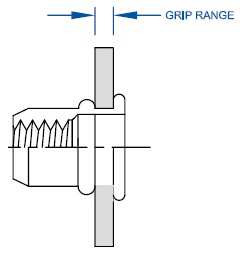
Determining the length of the rivetnut is critical to ensure it will function as intended. If the rivetnut is applied over or under the specified grip range, it will not work properly. Be sure to accommodate for the “theoretical” grip versus the “actual” grip. While two pieces of sheet metal each are .055 thick, it doesn’t necessarily mean that the actual grip will be .110. Burrs or bends in the sheet metal could affect the theoretical grip.
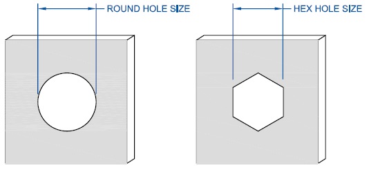
Hole Size & Shape:
The Rivetnut will only work if it is used within the prescribed hole size. The design engineer should calculate the manufacturing tolerances of the hole to ensure proper fit so that interference issues will not arise at a later time. Holes should be round for round body rivetnuts, and hex for hex body rivetnuts. Oval, Square or out-of-round shapes require the rivetnut to be custom produced.
Tool Clearance: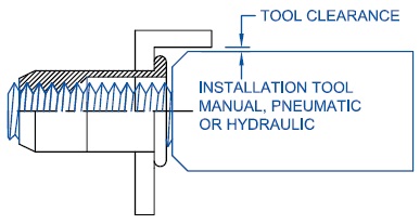
There must be adequate clearance above the hole so that riveting equipment can access the hole to be riveted without interference. Be sure to incorporate the riveting equipment in the design phase to prevent the need for customized and potentially costly tooling modifications.
Head Clearance: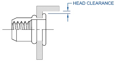
Axial access is required on the primary sheet being riveted to allow for the flange to overlap the hole without interference. When designing the primary hole, make sure to calculate the head diameter and its tolerances and layout the foot print of the head around the hole. This is especially critical when riveting near other hardware, next to bends or folds, extrusions and/or cutouts on the sheet metal.
Blind Side Clearance:
Since the blind side of the rivetnut is designed to form into a secondary flanged bearing surface, it is important to leave room forthe flange to expand and to seat properly. Make sure the backside can accommodate the entire rivet before riveting. Testing should be done in the design phase to calculate what distances are needed.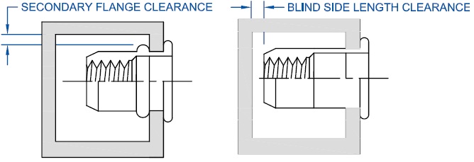
Galvanic Action:
Galvanic action is seldom considered in design but can often be one of the hidden causes of failures. Galvanic corrosion is accelerated electromechanical corrosion produced when a noble metal is in contact with another less noble metal, both being in a corrosive medium (such as damp air). The less-noble metal corrodes at a faster rate than normal while the noble metal acquires greater corrosion protection. For an example, an aluminum (less-noble metal) rivet in copper (more-noble metal) would cause aluminum to corrode at an accelerated rate while the copper would be virtually unaffected. Should you be in a position of having to join two dissimilar metals, be sure to consult the galvanic series table.
Corrosion Protection:
The corrosion factor of a particular rivet is dependent on the corrositivity of the base metal, the protection layer (plating), and the conversion layer (chromate). Being that the most cost-effective material to produce is steel, most prefer to protect the steel with a plating such as Zinc and a chromate. Rivetnuts require a specialized plating & wax, therefore it is highly suggested that the manufacturer perform this task. Do not attempt to reprocess rivetnuts! For standard performance, a SST rating (salt spray test) is about 48 hours until Red Rust. Other platings such as Zinc alloy’s (ZiNi, ZnFe, ZnTi) are available which can extend the SST rating to 840 hours until red rust. Be sure the plating is tested by the manufacturer per ASTM B117 standard and that the manufacturers’ lab is proficiency tested semi-annually.
CAD Files

CAD models are available for download (.dxf .dwg .IGES .SLDPRT) upon request by emailing engineering@rivet.com.
| Catalog Page | Complete Catalog |
|---|---|
 |
 |